

Bussing Sequence
Interiors are designed to accommodate top or bottom feed. Regardless of which is specified, the uppermost pole is always on “A” phase; the second pole down is always on “B” phase, and the third pole down is always on ”C” phase (assuming 3Ø panel).
As standard, branch breakers shall be mounted at the top of the panel with “spaces” at the bottom, regardless of the direction panel is fed.
All breakers have bolted connections except plug-in type. The panel design provides bracing up to 200,000A IR UL short circuit rating.
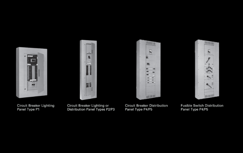
Panelboard Ratings (Updated June 2014 with release of Revised P1 design)
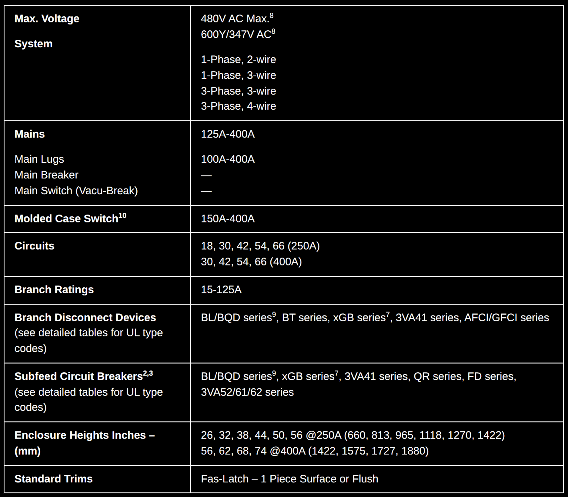
P1 Revised
P2
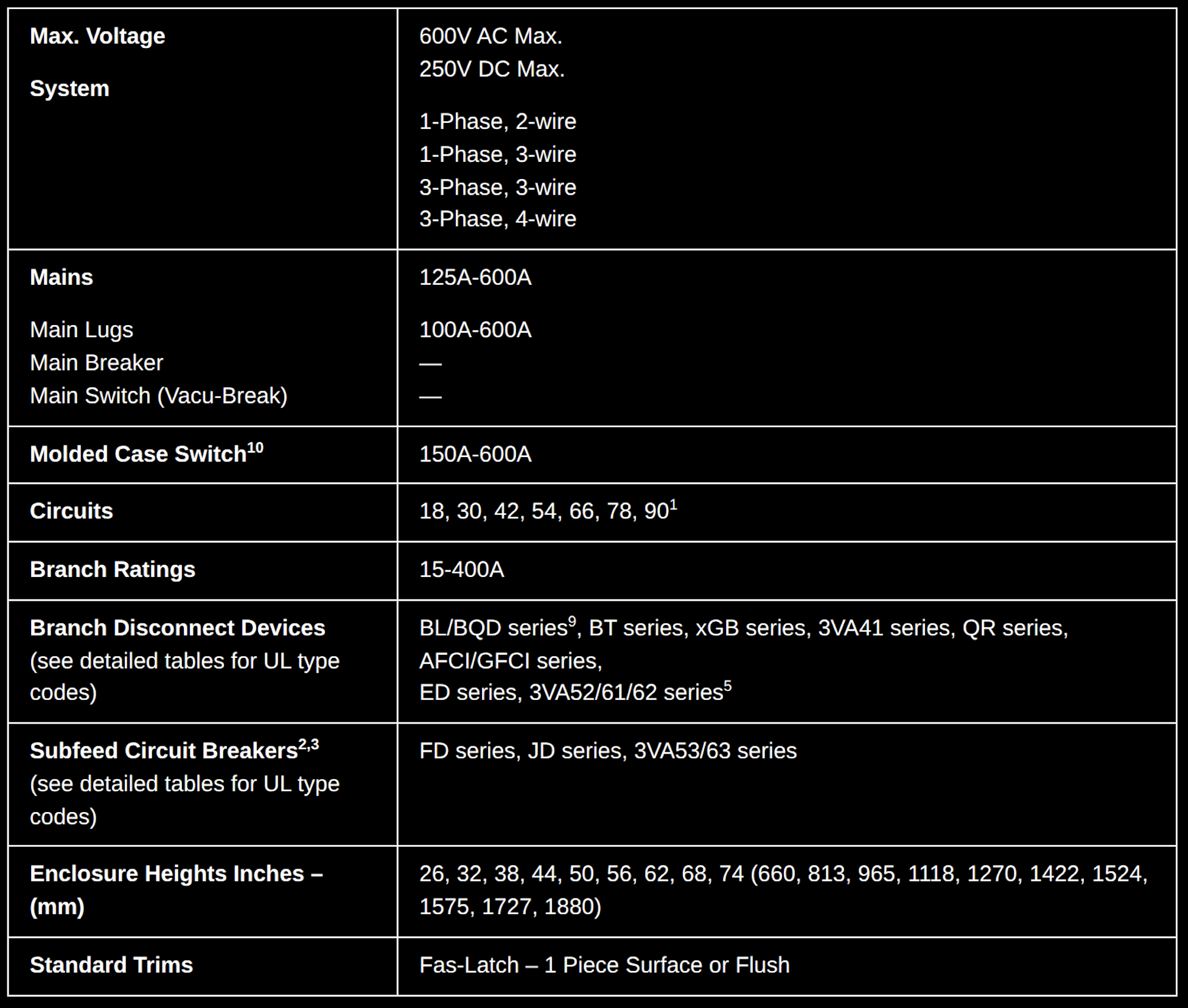
P3
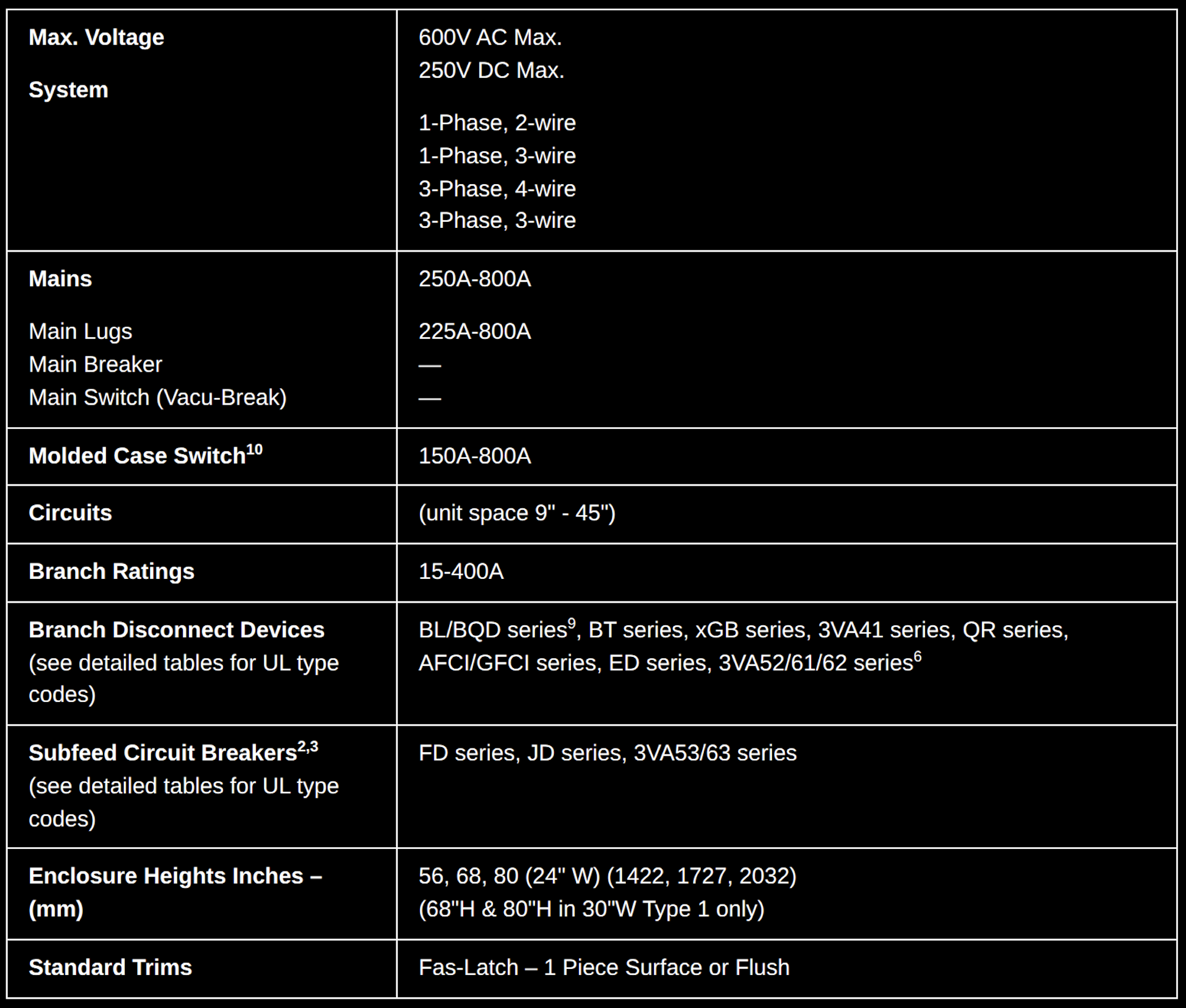
P4
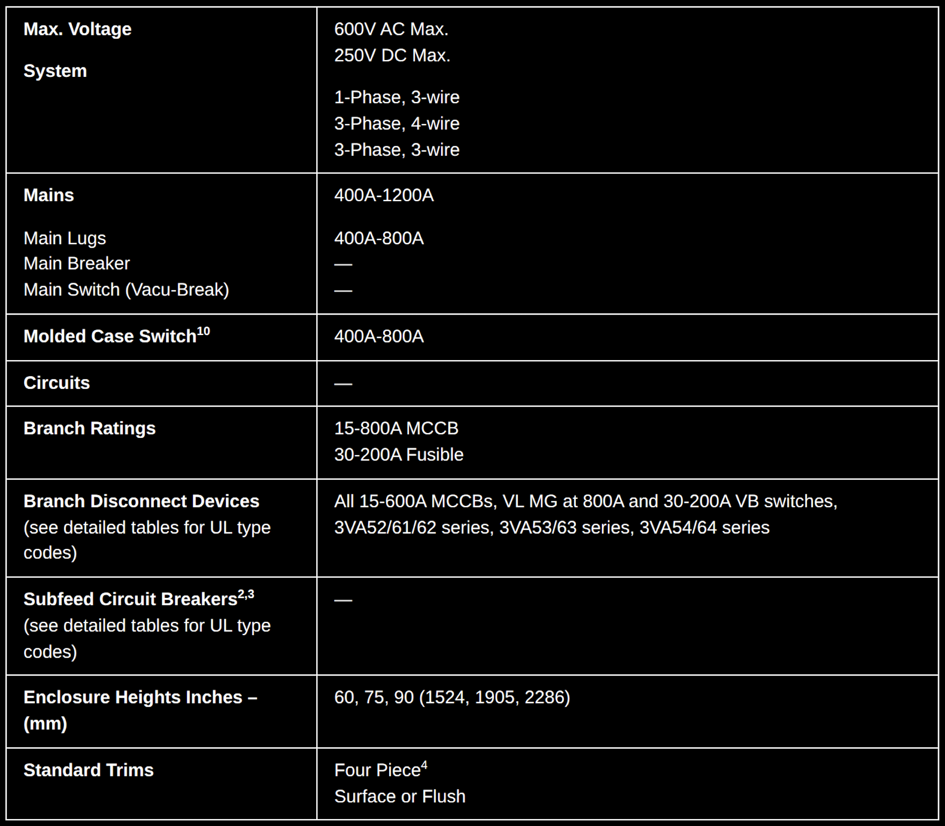
P5
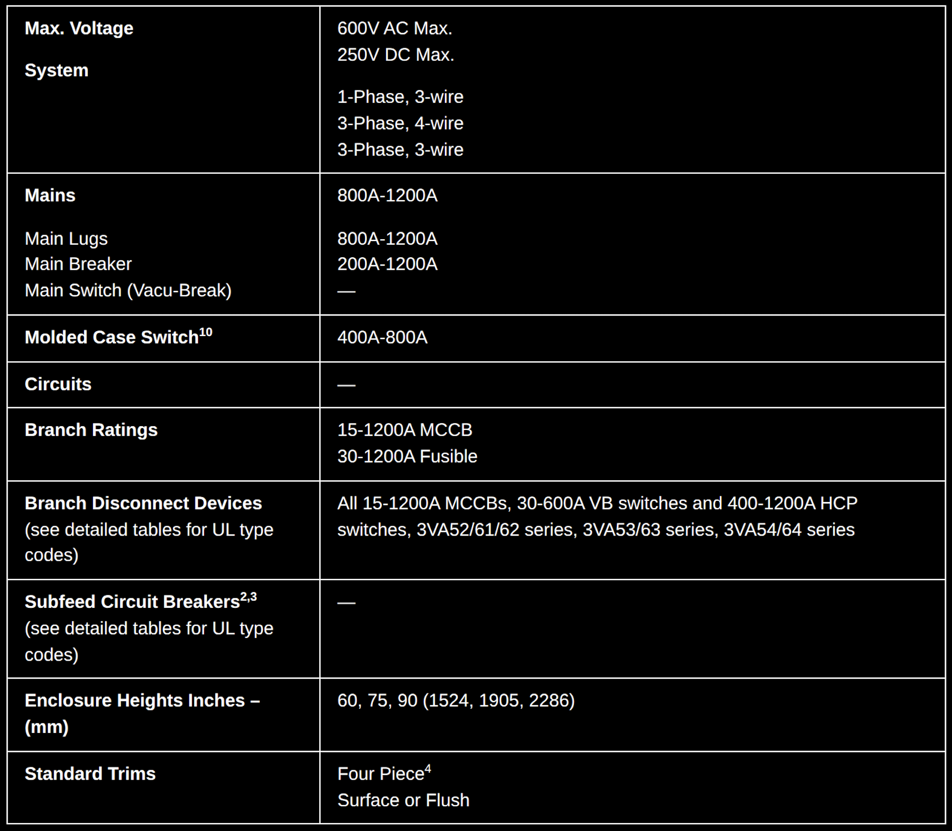
- Functional pricing is based on circuits shown. However, the panel can be figured with less circuits.
- P1 can have max. 1 subfeed breaker when Subfeed Space is available. P2 and P3 can have up to (2) FD subfeed breakers.
- JD and FD breakers are mounted vertical. Limitations apply.
- Trim ring provided for flush applications.
- A maximum of (4) QR/3VA52/3VA62/61 breakers may be mounted in a P2 Panel and are single mounted.
- A maximum of (6) QR/3VA52/3VA62/61 breakers may be mounted in a P3 panel in 24" wide enclosure. Up to 12 can be installed with 30" wide enclosure.
- P1 panels with xGB/3VA41 are limited to interiors for xGB/3VA41 breakers only.
- Factory assembled P1 has capability of 600Y/347V AC system when the proper breakers are selected.
- BQD6 is not UL Listed. Only for CUL and CSA panels.
- MCS can be used as a Main but not as a service disconnect or a branch.
Download the Siemens Panelboard Technical Document here.